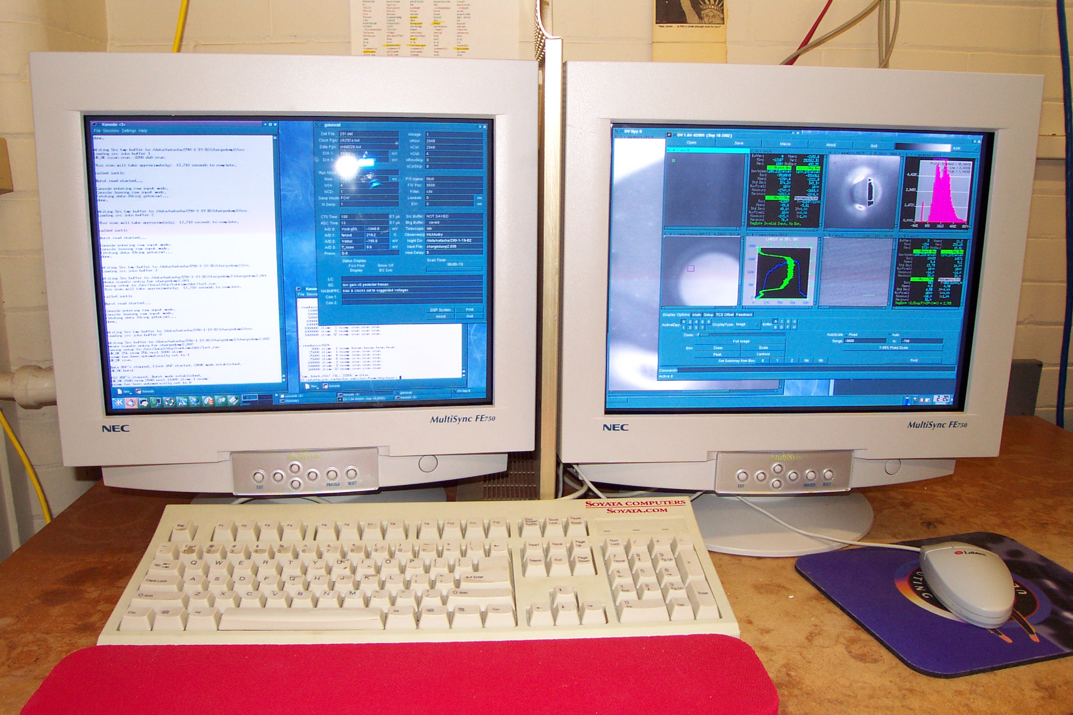
 This is the dual monitor setup used to control the infrared
camera (left monitor) and display images taken with the infrared camera
(right monitor).
This is the dual monitor setup used to control the infrared
camera (left monitor) and display images taken with the infrared camera
(right monitor).
Click image for larger (1600 x 1200 pixel) image.
This is the dual monitor setup used to control the infrared
camera (left monitor) and display images taken with the infrared camera
(right monitor).
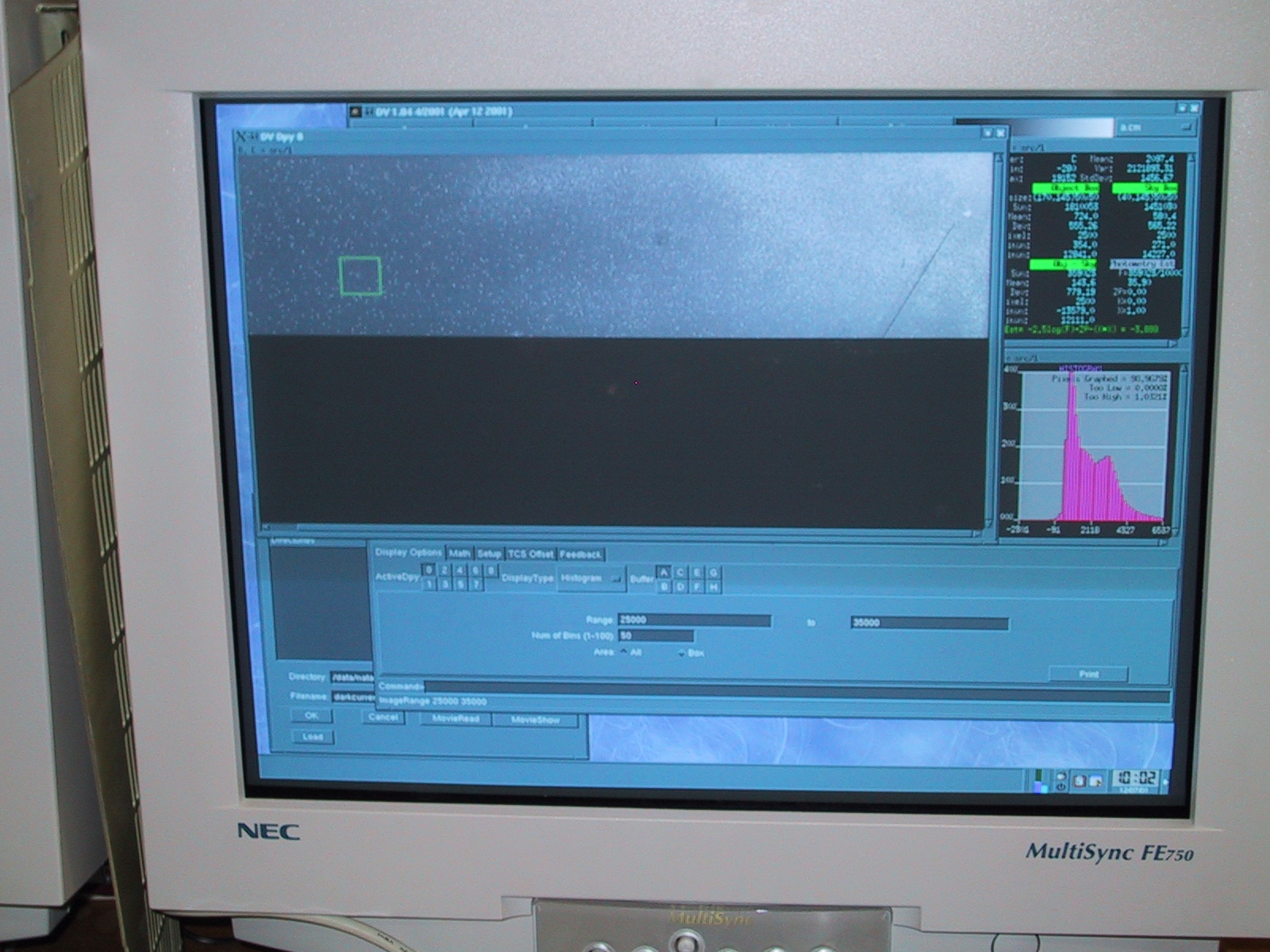 This picture shows a close up of the right monitor. The
infrared images (in FITS format) are displayed using software called DV or
Data Viewer, written by NASA
Infrared Telescope Facility.
This picture shows a close up of the right monitor. The
infrared images (in FITS format) are displayed using software called DV or
Data Viewer, written by NASA
Infrared Telescope Facility.
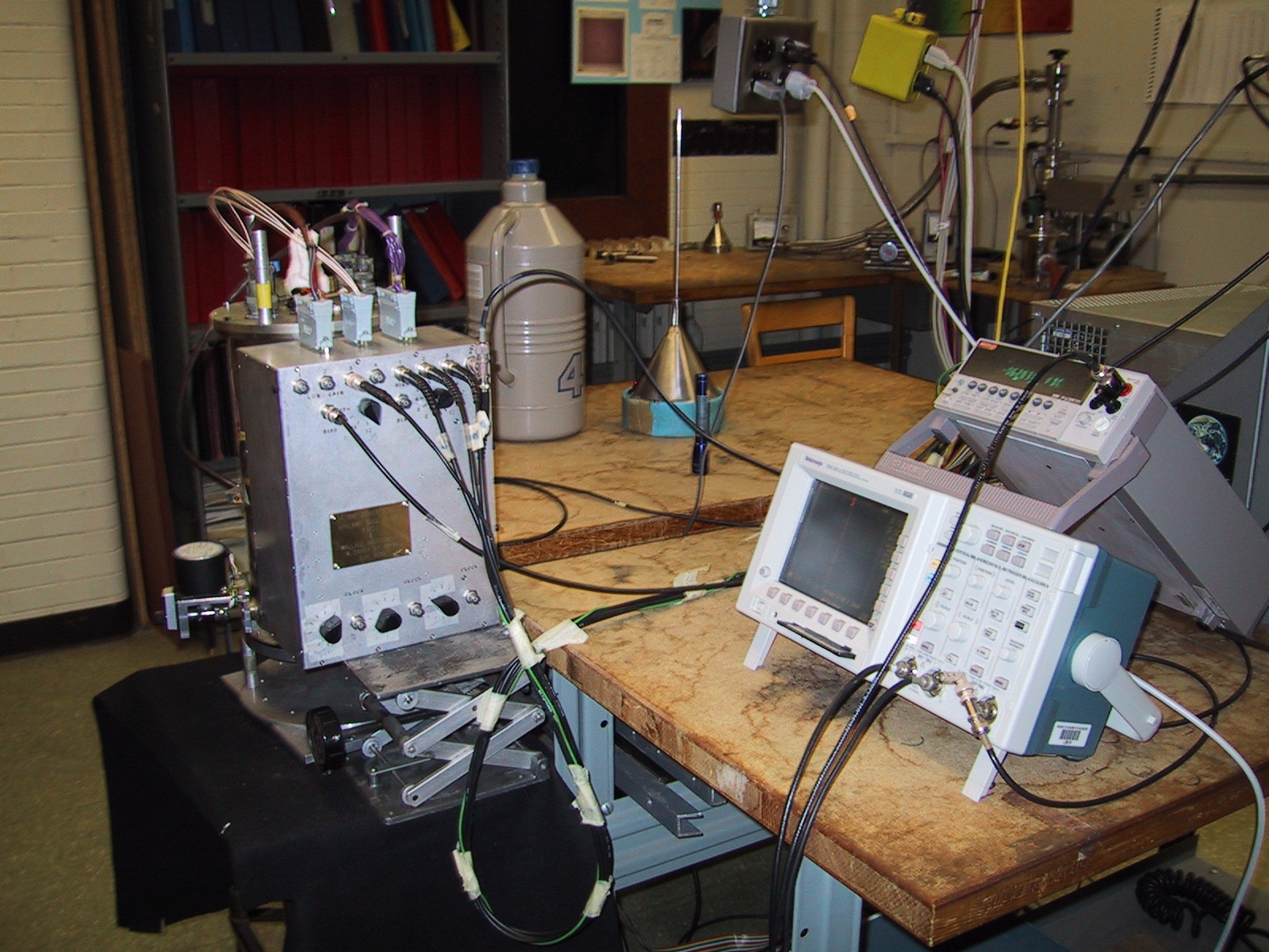
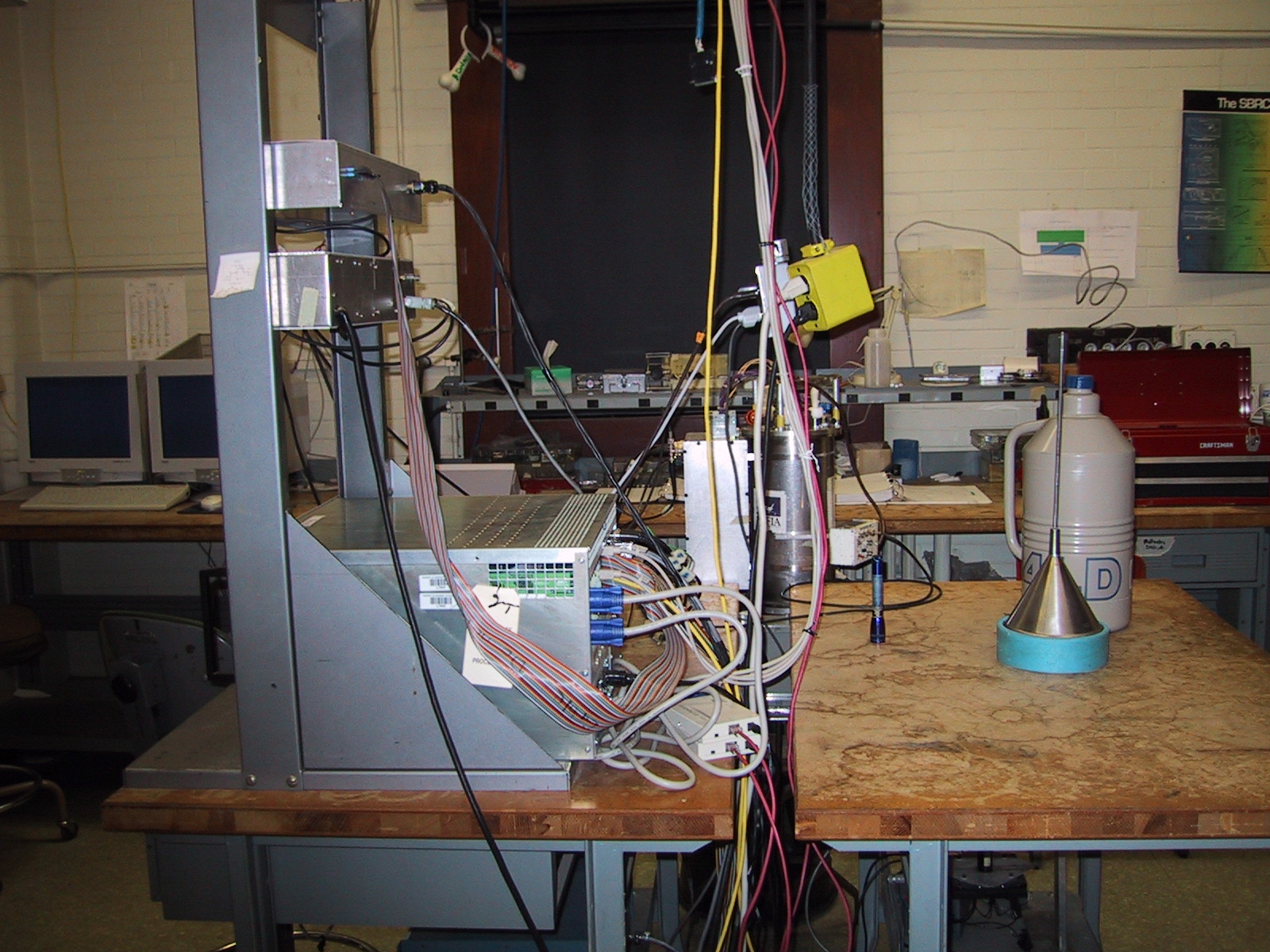 This picture shows the computer which controls the infrared array camera.
The computer (large box, left forefront) is also connected to several other
electronics boxes such as the stepper motor controller (middle location on
the rack) and the patch-panel box (top of rack).
This picture shows the computer which controls the infrared array camera.
The computer (large box, left forefront) is also connected to several other
electronics boxes such as the stepper motor controller (middle location on
the rack) and the patch-panel box (top of rack).
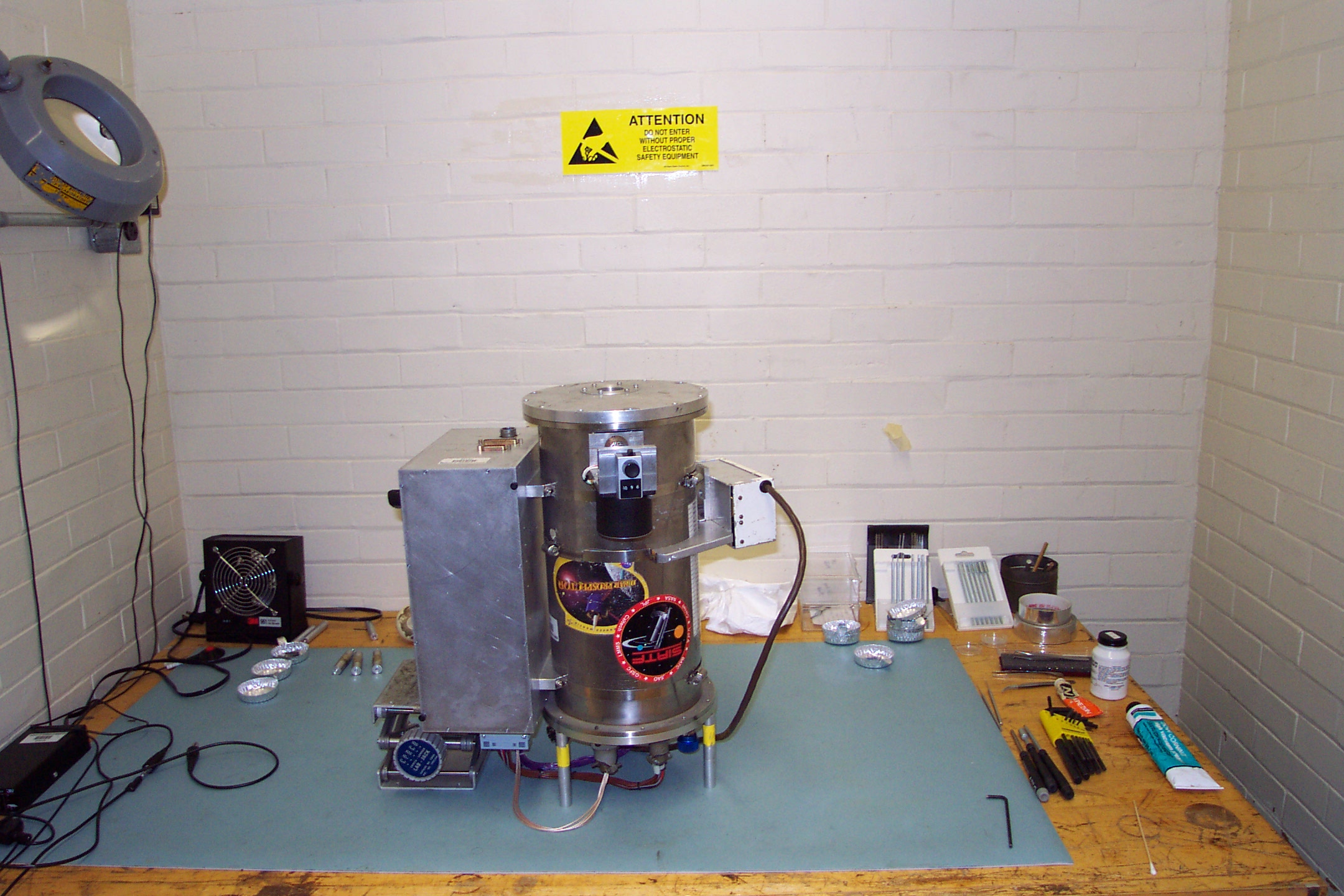
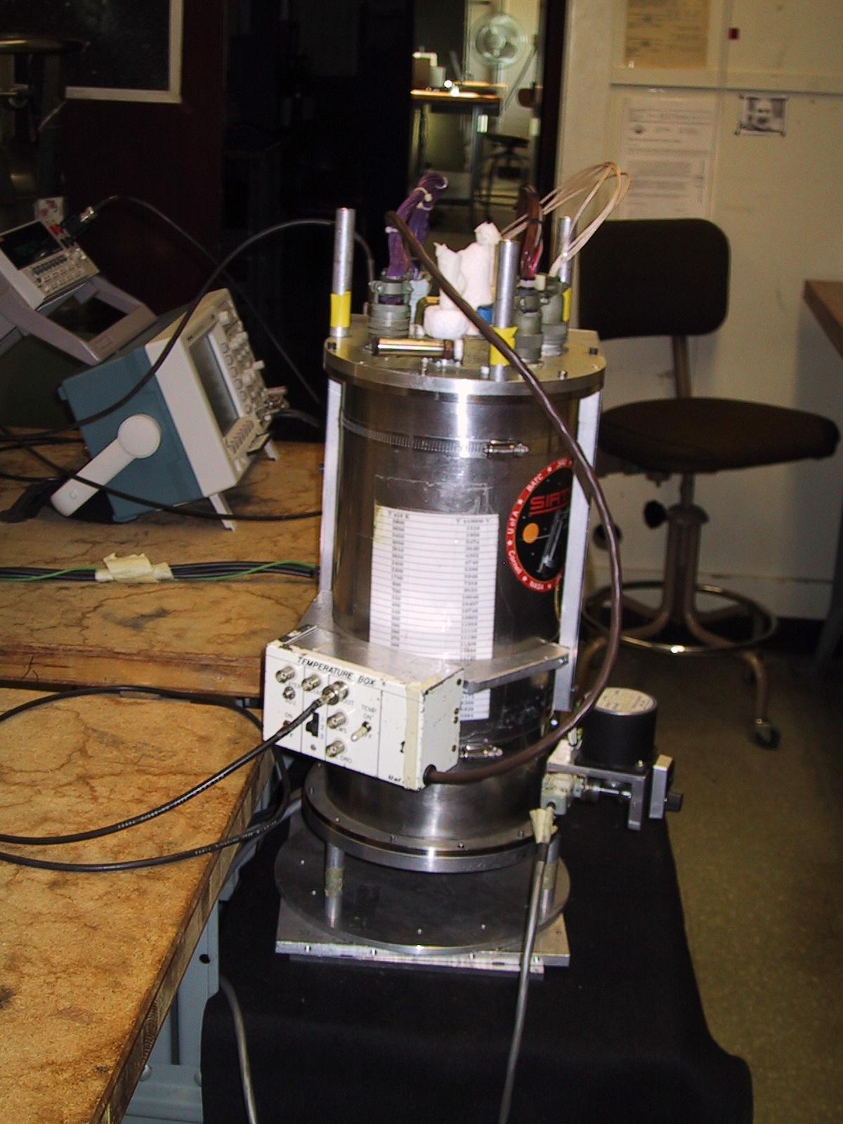 Here is the infrared camera/dewar. The camera is currently operating
at cryogenic temperatures, and frost/ice build-up is clearly visible
on the top of the camera. We use liquid nitrogen (77K = -196C = -320F)
and liquid helium (4.2K = -268.8C = -451.8F) for cryogenic coolants.
Here is the infrared camera/dewar. The camera is currently operating
at cryogenic temperatures, and frost/ice build-up is clearly visible
on the top of the camera. We use liquid nitrogen (77K = -196C = -320F)
and liquid helium (4.2K = -268.8C = -451.8F) for cryogenic coolants.
 This is the other side of the infrared camera/dewar showing another
electronics control box, Tektronics digital oscilloscope and Keithley
digital multimeter.
This is the other side of the infrared camera/dewar showing another
electronics control box, Tektronics digital oscilloscope and Keithley
digital multimeter.
Click image for larger (2160 x 1440 pixel) image.
 This is our infrared camera/dewar upside down. It is ready to be opened in
our electro-static discharge safe room (notice yellow warning and blue matt).
Two electronics boxes are still attached to the sides of the camera/dewar
(cylinder). The larger box contains our bias level, clock level, and signal
amplification circuits. The smaller box contains diagnostics and temperature
sensor circuits.
This is our infrared camera/dewar upside down. It is ready to be opened in
our electro-static discharge safe room (notice yellow warning and blue matt).
Two electronics boxes are still attached to the sides of the camera/dewar
(cylinder). The larger box contains our bias level, clock level, and signal
amplification circuits. The smaller box contains diagnostics and temperature
sensor circuits.
 This is a close-up for a better look at the entrance window.
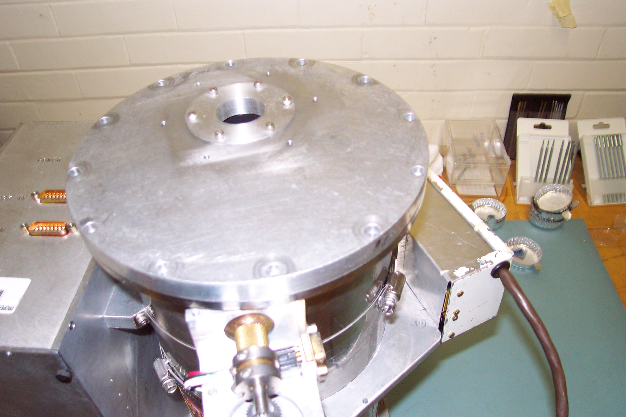
 The bottom plate was removed (placed to the lower right). You are now looking
at the super-insulation covering the heat shield of the liquid nitrogen (LN2)
container. The outside gears for the stepper motor are visible at the
bottom center of the image.
The bottom plate was removed (placed to the lower right). You are now looking
at the super-insulation covering the heat shield of the liquid nitrogen (LN2)
container. The outside gears for the stepper motor are visible at the
bottom center of the image.
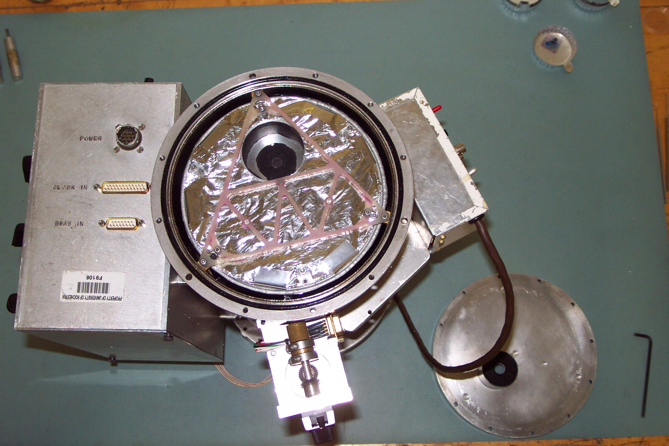
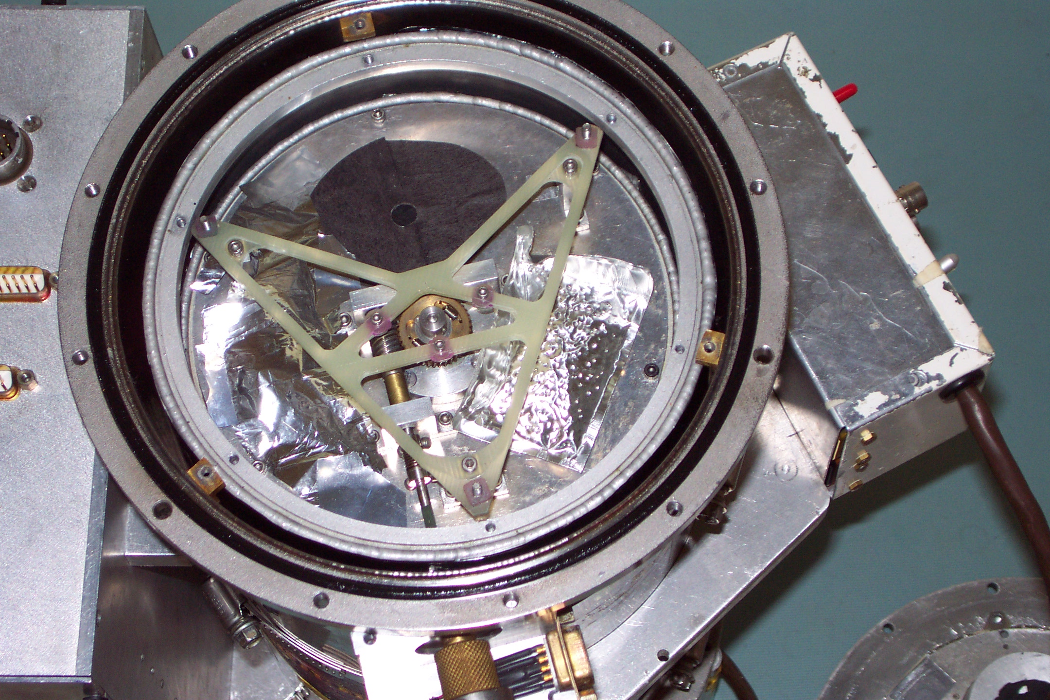 The LN2 shield cover plate has been removed. This is the liquid helium (LHe)
shield cover plate. The LHe shield cover plate also holds the dessicant pack
(foil pack with holes - right of center, about 4 o'clock). You can also see
the filter wheel gears that attach to the filter wheel shaft and stepper
motor (see above image). Currently the filter wheel is centered on our
"cold dark slide" or cold opaque light blocker (equivalent to a closed shutter).
The LN2 shield cover plate has been removed. This is the liquid helium (LHe)
shield cover plate. The LHe shield cover plate also holds the dessicant pack
(foil pack with holes - right of center, about 4 o'clock). You can also see
the filter wheel gears that attach to the filter wheel shaft and stepper
motor (see above image). Currently the filter wheel is centered on our
"cold dark slide" or cold opaque light blocker (equivalent to a closed shutter).
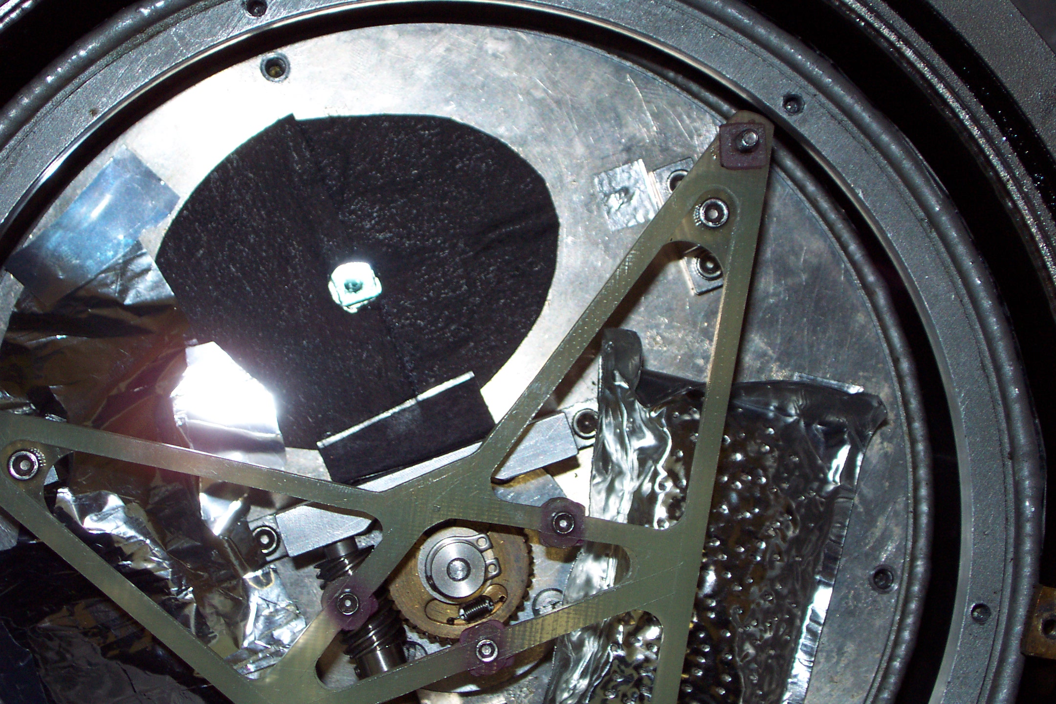 This image shows a close-up of the LHe shield cover plate. The filter
wheel has been moved to a visible broad band filter (lamda_c = 550 nm,
band width = 300 nm). You can sort of see through this filter to the
Lyot stop below it (0.82 mm diameter).
This image shows a close-up of the LHe shield cover plate. The filter
wheel has been moved to a visible broad band filter (lamda_c = 550 nm,
band width = 300 nm). You can sort of see through this filter to the
Lyot stop below it (0.82 mm diameter).
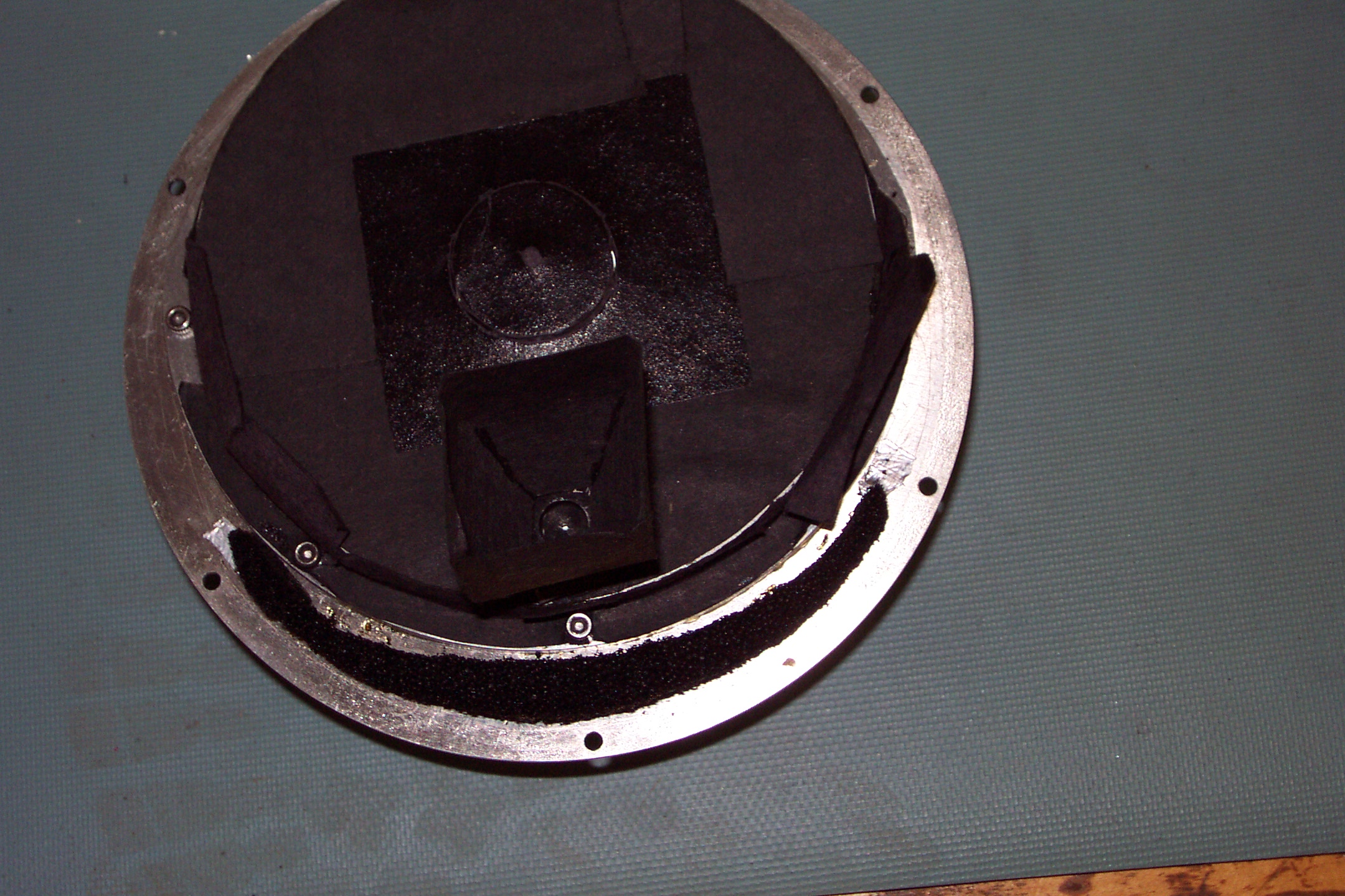 This is the bottom side of the LHe shield cover plate and filter wheel
housing. This faces the infrared detectors. The Lyot stop hole is the
small pinhole surrounded by black, near the bottom (6 o'clock) (not the
hex screw or the screw hole).
This is the bottom side of the LHe shield cover plate and filter wheel
housing. This faces the infrared detectors. The Lyot stop hole is the
small pinhole surrounded by black, near the bottom (6 o'clock) (not the
hex screw or the screw hole).
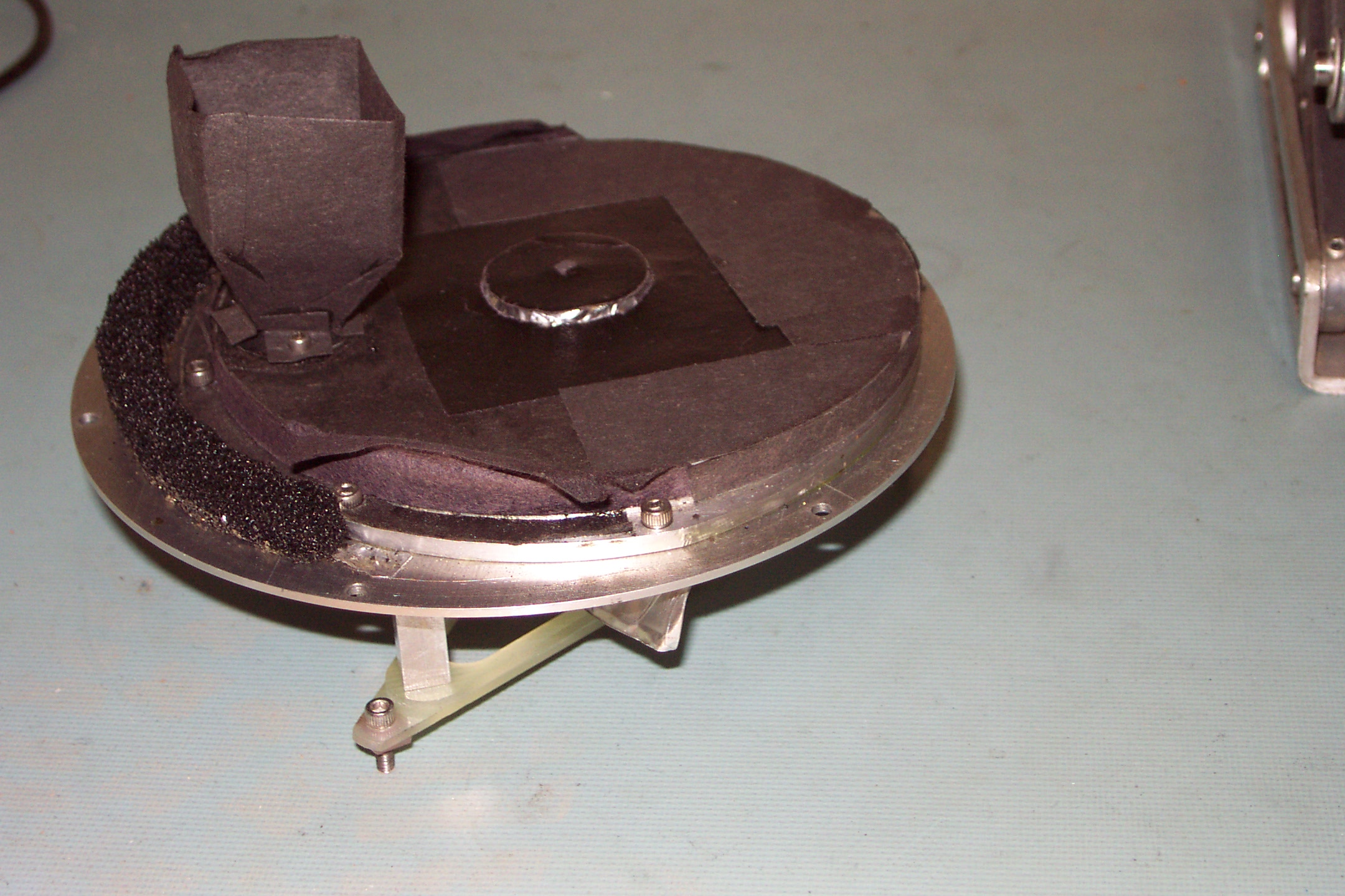 This is a side view of the LHe shield cover plate and filter wheel
housing. A light baffle surrounds the Lyot stop.
This is a side view of the LHe shield cover plate and filter wheel
housing. A light baffle surrounds the Lyot stop.
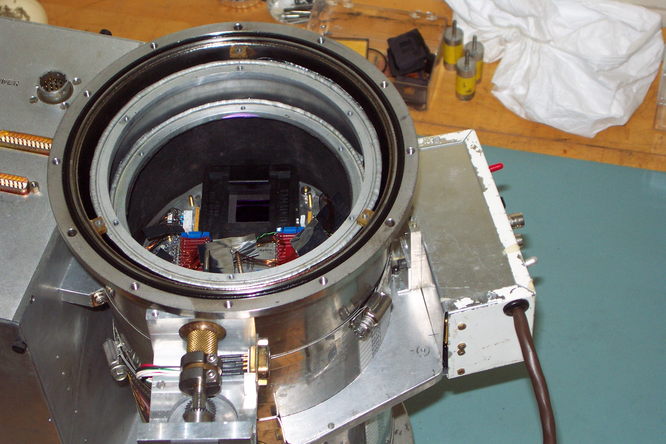
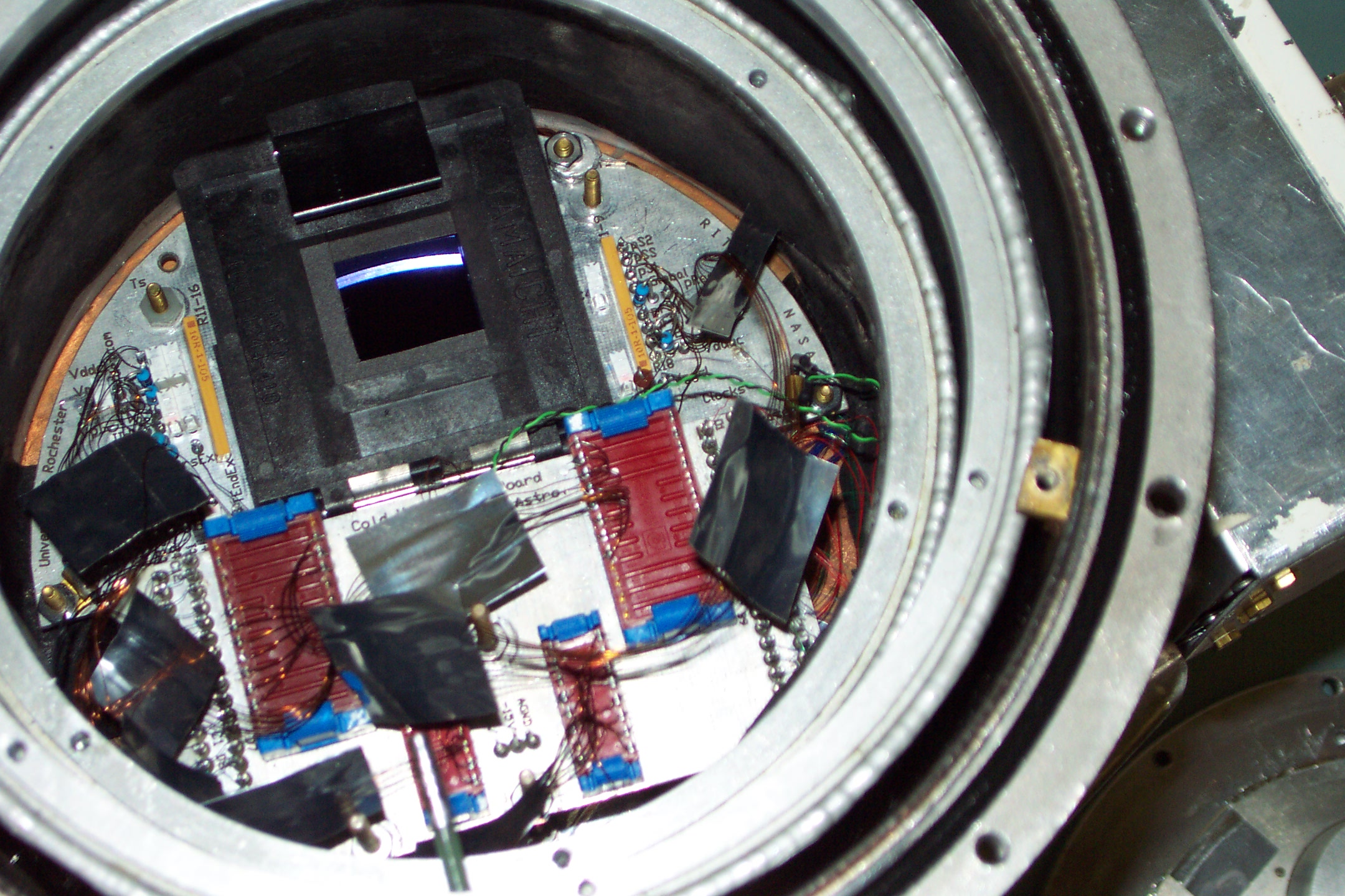 This image shows the view of the camera/dewar with the LHe shield cover
plate and filter wheel housing removed. Our circuit board (fanout board)
for holding the infrared detector, as well as the dewar "cold work surface"
for dewar electrical connections, are visible.
This image shows the view of the camera/dewar with the LHe shield cover
plate and filter wheel housing removed. Our circuit board (fanout board)
for holding the infrared detector, as well as the dewar "cold work surface"
for dewar electrical connections, are visible.
 The infrared detector is held in a socket holder (black clamping socket,
affectionately known as the "toilet seat"). The dewar wiring is special
small gauge wire that has very low thermal conductance. The temperature sensing
diode is the circular piece held down by a screw and nut, located at the
upper right corner of the socket holder. Numerous other electrical components
can be seen such as resistors (small blue or long yellow/orange) and capacitors
(white blocks).
The infrared detector is held in a socket holder (black clamping socket,
affectionately known as the "toilet seat"). The dewar wiring is special
small gauge wire that has very low thermal conductance. The temperature sensing
diode is the circular piece held down by a screw and nut, located at the
upper right corner of the socket holder. Numerous other electrical components
can be seen such as resistors (small blue or long yellow/orange) and capacitors
(white blocks).
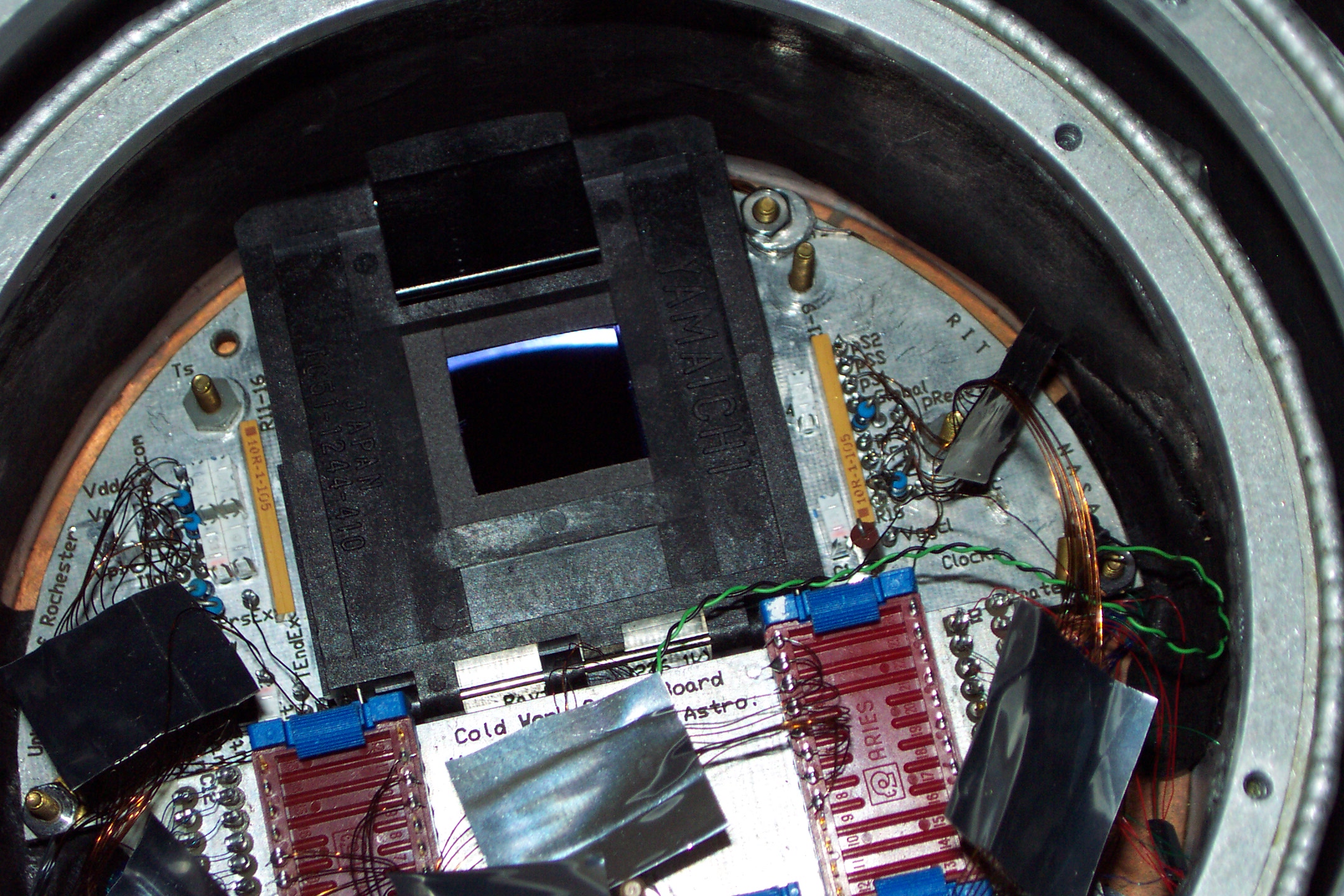
 Another view of the open camera. At about 12 o'clock on the LHe shield
there is a bright purple reflection off of the InSb detector AR coating
surface from my flash bulb (some people may find that to be humorous irony,
but the AR coating is optimized for the infrared, not visible and the angle
of reflection is much larger than typical incident radiation).
Another view of the open camera. At about 12 o'clock on the LHe shield
there is a bright purple reflection off of the InSb detector AR coating
surface from my flash bulb (some people may find that to be humorous irony,
but the AR coating is optimized for the infrared, not visible and the angle
of reflection is much larger than typical incident radiation).
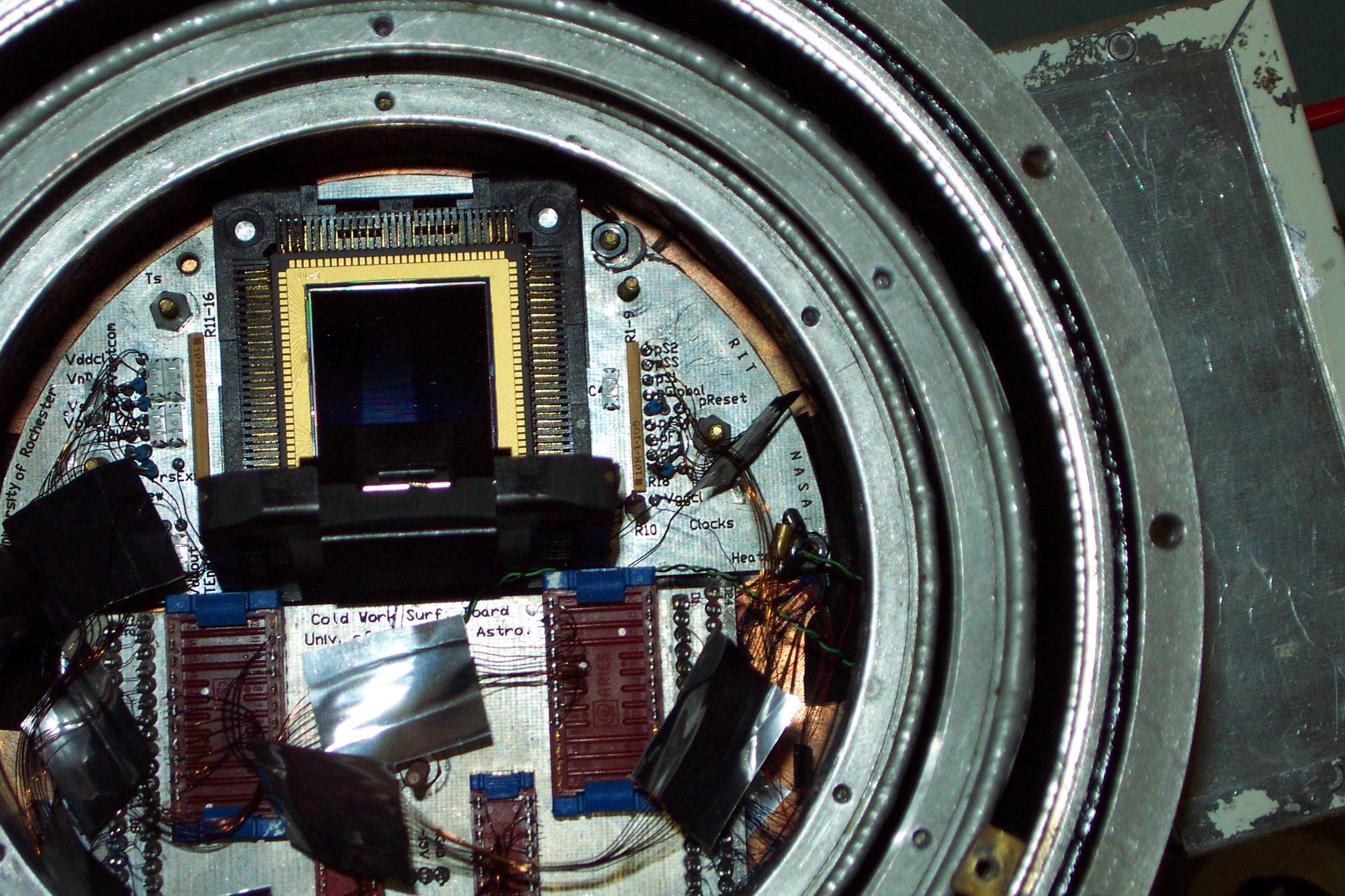 Close up view of the detector with the toilet seat open. (Note: I couldn't
center the detector well because the InSb surface kept reflecting a very
bright purple light from my flash bulb. See above picture note.) You can
see the micro-fine gold wires that attach the InSb detector and multiplexer
to the gold pads of the leadless chip carrier (LCC). This infrared array
detector is a 1024 x 1024 pixel InSb detector array which is sensitive
to wavelengths from 0.5 to 5.3 micrometers. The InSb is bump-bonded to a
SB 226 multiplexer readout produced by
Raytheon RIO for NASA. The device is a step on the
road to the detectors for NASA's
Next Generation Space Telescope (NGST) .
Close up view of the detector with the toilet seat open. (Note: I couldn't
center the detector well because the InSb surface kept reflecting a very
bright purple light from my flash bulb. See above picture note.) You can
see the micro-fine gold wires that attach the InSb detector and multiplexer
to the gold pads of the leadless chip carrier (LCC). This infrared array
detector is a 1024 x 1024 pixel InSb detector array which is sensitive
to wavelengths from 0.5 to 5.3 micrometers. The InSb is bump-bonded to a
SB 226 multiplexer readout produced by
Raytheon RIO for NASA. The device is a step on the
road to the detectors for NASA's
Next Generation Space Telescope (NGST) .
Last modified: Wed Jan 7 12:23:27 EST 2004